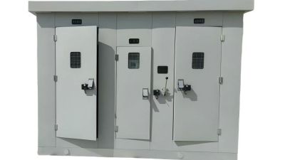
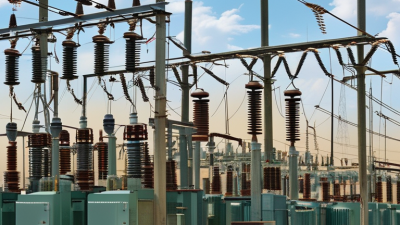
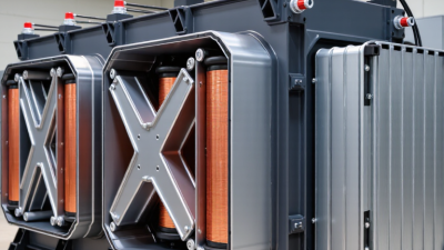
Picking out the right Power Station Transformer isn't just a matter of checking its capacity. It’s really about making a trusted, long-term choice. You’ve got to ensure it matches up with voltage needs, load patterns, fault levels, cooling methods, insulation standards, and the specific conditions at your site. For example, a transformer sitting near a coastal plant will have to handle salt, humidity, and potential corrosion, while one used for solar projects might deal with more dramatic daily swings in load. It’s all about understanding the environment and how the transformer will perform over time.
According to the International Energy Agency in their report on Electricity Grids and Secure Energy Transitions, the amount of money needed for grid investments each year will have to go above USD 600 billion by 2030. That kind of growth means there’s a higher demand for reliable transformers, but it’s worth noting that supply isn’t always quick or flexible. The U.S. Department of Energy points out that big power transformers can take up to three years just to be made and delivered. So, if you pick the wrong specs, it can really mess up your project schedule, spare parts planning, and revenue from operations.
Dr. T. V. Oommen, who’s been deep into transformer research, once said, “The life of a transformer is determined by the life of its insulation system.” And honestly, that’s a key point to keep in mind every time you’re making a purchase. It’s smart to look into things like thermal aging, moisture management, dissolved gas analysis, short-circuit strength, and factory testing records. Standards like IEC 60076 and IEEE C57 give you good technical guidelines, but just following standards doesn’t automatically mean you’ll find the perfect fit for your specific needs.
Let’s be real — no choice is ever perfect. Picking a larger transformer might give you some extra capacity down the road but could also mean more energy losses and higher installation costs. On the flip side, going for a cheaper option might save you money upfront but could lead to costly surprises if your monitoring isn’t solid. Basically, the best decision comes down to matching solid engineering data with what your plant really needs. That means being transparent with data, consulting experienced people, and honestly weighing what you don’t know yet — because that’s often where the biggest risks hide.
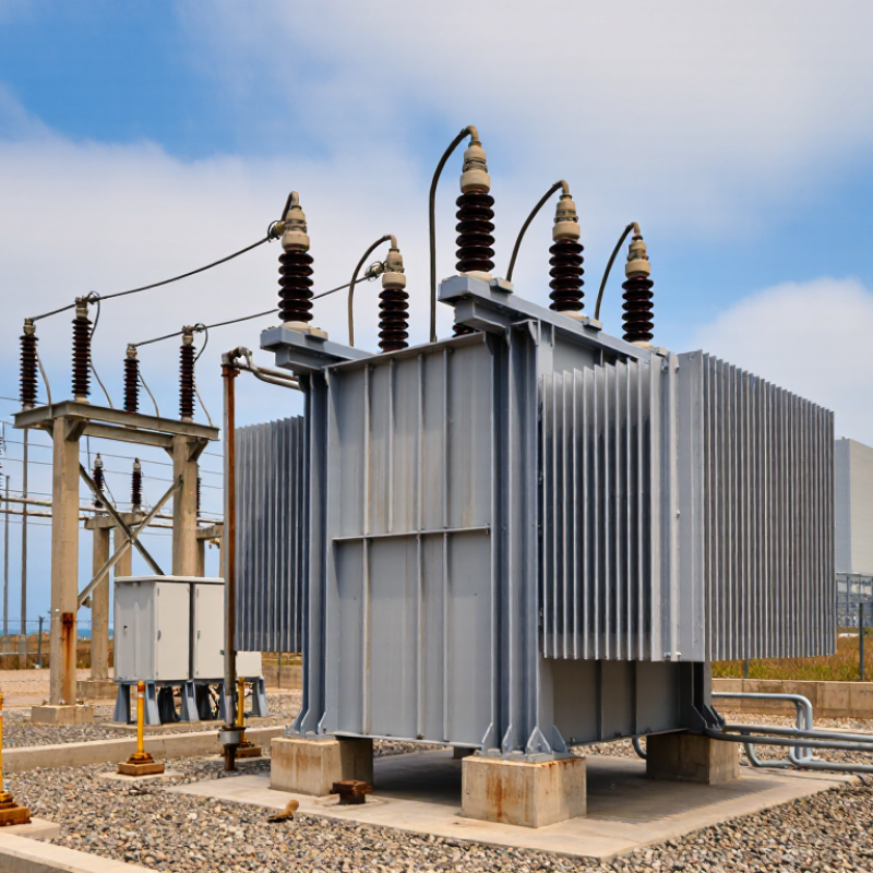
Define the Role and Operating Conditions of the Power Station Transformer
How to Choose a Power Station Transformer?
A Power Transformer Station may serve several duties. It can raise generator voltage for grid transmission or reduce voltage for plant equipment. Define this role before comparing ratings, prices, or delivery schedules. A transformer selected for the wrong duty may operate safely but waste energy continuously. That mistake is expensive.
Review the operating conditions in measurable terms. Record the highest and lowest voltage, system frequency, expected load profile, and short-circuit level. Check whether motors, furnaces, or converters create harmonics. Ambient temperature, altitude, humidity, dust, and salt exposure also affect insulation and cooling. A cabinet near a dusty road needs different protection than one inside a clean control building. Small details matter.
Choose the rated power with realistic growth in mind. Avoid excessive oversizing, because light-load losses can remain high. Confirm the cooling method, tap-changer range, insulation level, noise limit, and protection scheme with qualified engineers. Site tests should include winding resistance, insulation condition, oil quality, and protective relay operation. Keep clear records. They support future maintenance and independent review. A neat spreadsheet can still mislead. Real load measurements may expose assumptions that looked reasonable during design. The final selection should match actual duty, not merely the largest available rating.
Calculate Capacity, Load Demand, and Future Expansion Requirements
How to Choose a Power Station Transformer?
Begin with measured demand, not connected load. List motors, heating systems, converters, auxiliary equipment, and their operating schedules. The basic sizing formula is kVA = kW ÷ power factor. Apply demand and diversity factors, then check motor starting current, harmonics, ambient temperature, and altitude. Record peak demand carefully.
Suppose the measured peak is 2,400 kW at a 0.90 power factor. The present apparent load is about 2,667 kVA. Adding a 20% engineering margin gives 3,200 kVA. A planned 15% expansion raises the requirement near 3,680 kVA. This example may look simple, but poor load measurements can distort the result. A spreadsheet can look precise and still be wrong.
Future planning deserves evidence. The International Energy Agency’s Electricity 2024 report forecasts global electricity demand to grow by about 3.4% annually from 2024 to 2026. New electrified processes, cooling systems, and data loads may increase station demand faster than expected. The U.S. Department of Energy estimates distribution transformers consume roughly 60 billion kWh annually in the United States, making efficiency and realistic loading important. Compare projected kVA with the transformer’s continuous rating, emergency rating, voltage regulation, and thermal limits under IEEE C57.91 guidance. Leave physical space for a second unit, future switchgear, and cable routes. Do not guess. Recheck the design after twelve months of operating data.
How to Choose a Power Station Transformer? - Calculate Capacity, Load Demand, and Future Expansion Requirements
The following example uses a 33/11 kV distribution substation. Transformer capacity should be selected from the calculated maximum demand, power factor, allowable loading, starting requirements, and planned future expansion.
| Load Category |
Connected Load
(kW) |
Demand Factor |
Maximum Demand
(kW) |
Power Factor |
Estimated Demand
(kVA) |
Design Consideration |
| Industrial motors and drives |
2,400 |
0.75 |
1,800 |
0.88 |
2,045 |
Check motor starting current and voltage dip. |
| Process heating and furnaces |
1,200 |
0.80 |
960 |
0.95 |
1,011 |
Consider harmonic content from power-electronic controls. |
| Building services and HVAC |
700 |
0.70 |
490 |
0.90 |
544 |
Allow for seasonal cooling and ventilation peaks. |
| Lighting and small power |
350 |
0.85 |
298 |
0.95 |
314 |
Include emergency and control-room services. |
| Pumps and utility systems |
500 |
0.65 |
325 |
0.85 |
382 |
Review duty, standby, and sequential starting conditions. |
| Total connected load |
5,150 |
— |
3,873 |
— |
4,296 |
Arithmetic sum before diversity between categories. |
| Coincidence adjustment |
— |
0.90 |
3,486 |
0.90 |
3,873 |
Apply only when operating schedules support the assumed coincidence factor. |
Transformer Capacity Selection
| Calculation Item |
Formula or Basis |
Result |
Selection Guidance |
| Present maximum apparent power |
S = P ÷ power factor = 3,486 kW ÷ 0.90 |
3,873 kVA |
Use diversified demand rather than connected load. |
| Future expansion allowance |
Future kVA = 3,873 kVA × 20% |
775 kVA |
Replace 20% with the approved development forecast. |
| Required capacity before loading margin |
3,873 kVA + 775 kVA |
4,648 kVA |
Compare with standard transformer ratings. |
| Recommended standard rating |
Select the next suitable standard rating above 4,648 kVA |
5,000 kVA |
Verify thermal, voltage-drop, fault-level, and utility requirements. |
| Expected loading at present demand |
3,873 kVA ÷ 5,000 kVA × 100% |
77.5% |
Leaves approximately 22.5% nameplate capacity for planned growth. |
| Expected loading after forecast expansion |
4,648 kVA ÷ 5,000 kVA × 100% |
93.0% |
Confirm continuous loading limits and ambient-temperature derating. |
Technical and Future-Expansion Checklist
| Decision Dimension |
Recommended Review Point |
Example Requirement |
| Voltage ratio |
Match the high-voltage and low-voltage system ratings and confirm the required tap range. |
33/11 kV, with tap settings based on the network voltage study. |
| Operating mode |
Choose one transformer, parallel transformers, or an N+1 arrangement according to reliability needs. |
Two transformers may improve maintainability and supply continuity. |
| Short-circuit level |
Check transformer impedance and its effect on downstream fault current and switchgear ratings. |
Coordinate transformer impedance with the calculated bus fault level. |
| Motor starting |
Evaluate voltage dips caused by direct-on-line motors, large pumps, and compressors. |
Use reduced-voltage starting or variable-speed drives where necessary. |
| Ambient and installation conditions |
Account for altitude, ambient temperature, enclosure ventilation, indoor or outdoor installation, and fire protection. |
Apply manufacturer-confirmed derating when site conditions exceed design assumptions. |
| Harmonic loading |
Assess rectifiers, drives, data equipment, and renewable-energy converters that may increase transformer heating. |
Specify harmonic evaluation or a suitable K-factor design where justified. |
| Future expansion |
Reserve space, cable routes, protection capacity, cooling capability, and switchgear positions for future loads. |
Plan for an additional 20% demand increase over the present diversified load. |
| Efficiency and losses |
Compare no-load and load losses over the expected operating profile, not only the purchase price. |
Evaluate lifetime energy cost at typical and peak loading. |
Calculation note: Apparent power is calculated using S (kVA) = P (kW) ÷ power factor. Demand factors and coincidence factors must be supported by operating data, load schedules, or an approved engineering study. The 5,000 kVA selection shown is an illustrative engineering example and must be validated against applicable electrical codes, utility rules, protection coordination, thermal limits, and site conditions.
Compare Transformer Designs, Ratings, and Cooling Methods
How to Choose a Power Station Transformer?
Choosing a power station transformer starts with comparing its design, rating, and cooling method. A two-winding transformer suits many straightforward voltage changes. A three-winding design can reduce equipment count when auxiliary loads need a separate supply. An autotransformer may save space, but it provides less electrical isolation. For a Step Up Transformer Power Station, verify the voltage ratio, frequency, impedance, and insulation level. A simple MVA comparison can mislead. Generator output, future expansion, and short-circuit conditions also affect the correct rating.
Cooling strongly influences reliability. ONAN cooling uses natural oil and air movement, while ONAF adds fans for higher loading. OFAF systems provide stronger heat control but need more auxiliary equipment and maintenance. Check the expected ambient temperature, altitude, noise limits, and emergency loading period. Tap changers deserve careful attention. Frequent voltage changes can increase mechanical and electrical stress. Field inspections should examine oil temperature, bushing condition, fan operation, and unusual vibration.
Tips: Leave practical headroom, not excessive capacity. Confirm ratings against IEC or IEEE requirements and the local grid code. Request temperature-rise data and factory test records. Compare lifecycle costs, not only the purchase price. A larger unit is not automatically safer; oversized equipment can operate inefficiently at light load. The best choice may still need revision after a detailed load study.
How to Choose a Power Station Transformer?
Transformer selection depends on rated power, system voltage, load profile, installation environment, and cooling method. The chart shows indicative upper rating levels commonly associated with major transformer cooling arrangements.
| Transformer design |
Typical application |
Typical cooling choice |
| Core-type power transformer |
Transmission and generation substations |
ONAN, ONAF, or OFAF |
| Shell-type transformer |
High short-circuit strength and compact layouts |
ONAN or forced-oil cooling |
| Autotransformer |
Voltage interconnection where the ratio is relatively close |
Usually ONAF or OFAF at high ratings |
Rating values are indicative upper levels in MVA, not fixed limits. The final rating must be verified against temperature rise, ambient conditions, altitude, impedance, short-circuit duty, overload requirements, and applicable IEC or IEEE standards.
Evaluate Voltage Levels, Efficiency, and Electrical Performance
Choosing a Power Transformer starts with voltage compatibility, not appearance or headline capacity.
Match the generator terminal voltage, transmission voltage, insulation level, and system frequency. Check future load growth too. A transformer sized only for today may become a bottleneck within five years.
Efficiency requires separate attention to no-load and load losses.
No-load losses continue while the transformer is energized. Load losses rise with current, often sharply during evening peaks.
A European Commission Ecodesign study estimated transformer losses at roughly 2.5% of electricity consumption in Europe. That figure makes small efficiency differences financially meaningful.
Ask for tested loss values, not only a single efficiency percentage. The number can mislead.
Electrical performance includes impedance, voltage regulation, vector group, tap-changer range, harmonics, and short-circuit withstand.
IEC 60076 provides the main testing framework for power transformers, including temperature-rise and dielectric tests.
A practical check is simple: compare the specified impedance with the station fault-level study.
Too little impedance can increase fault current; too much can weaken voltage stability.
Physical details matter. Inspect cooling clearances, oil temperature sensors, bushing access, and noise limits.
A field team also needs clear commissioning records. I would not trust a perfect spreadsheet without site measurements. Even experienced engineers can overlook cable length, ambient temperature, or an unexpected harmonic source.
Check Insulation, Protection, Safety, and Environmental Requirements
How to Choose a Power Station Transformer?
Insulation is the first practical checkpoint.
According to the U.S. Department of Energy’s “Transformers and the U.S. Electric Grid” report, nearly 70% of large power transformers were at least 25 years old. Aging paper insulation can weaken quietly, especially under heat, moisture, and repeated overloads. Specify suitable insulation levels, temperature rise, partial-discharge performance, and oil or gas testing methods. Do not trust nameplate data alone. Site conditions often tell a different story.
Protection must match the transformer, not merely the rated capacity.
Check differential protection, restricted earth-fault protection, overcurrent settings, Buchholz or equivalent gas detection, and pressure relief devices. IEC 60076-7 explains how loading and hot-spot temperature affect insulation life. A small setting error can create a large failure. I would request short-circuit calculations and relay coordination studies before approval. This step is sometimes rushed, and that is a weakness.
Safety and environmental requirements need equal attention.
The transformer should provide safe access, fire separation, spill containment, grounding, and clear emergency isolation points. IEC 60076-14 addresses liquid-immersed transformer design and testing considerations, including thermal and dielectric performance. Consider biodegradable insulating fluids where fire risk or water protection matters. However, “green” does not automatically mean suitable. Verify fire point, oxidation stability, maintenance needs, and end-of-life handling. A perfect checklist does not exist. Revisit assumptions after installation.
Assess Installation, Maintenance, Cost, and Supplier Support
Choosing an Hv Power Transformer starts with the installation site, not the catalogue. Measure access roads, crane capacity, foundation loading, clearances, and indoor ventilation. A transformer may fit electrically but still fail at the gate. Check salt, dust, flooding, and ambient temperature. Ask for verified loss data, insulation levels, noise limits, and protection interfaces. During a site review, mark cable entry points on the drawing. Small errors become expensive steel and concrete changes.
Maintenance planning should begin before energization. Confirm oil sampling points, temperature indicators, alarm contacts, and safe inspection access. Request a maintenance schedule based on operating hours and local conditions. Keep records of oil quality, bushing temperature, load history, and unusual sounds. A faint hum can be normal, but a new crackle deserves immediate investigation. Do not rely only on remote monitoring. It can miss a leaking gasket or damaged radiator valve.
Cost comparison must include transport, installation, testing, energy losses, spare parts, and planned outages. A low purchase price can hide weak documentation or difficult servicing. I would not pretend every cost forecast is exact; site changes often disrupt the estimate. Supplier support matters when a fault occurs at midnight. Check response times, commissioning assistance, training, drawings, test reports, and spare-part availability. Ask for references from installations with similar voltage, load, and environmental conditions. Good support is practical, documented, and available after delivery.
Transformer Neutral Grounding Resistors: 2024 Insights from the MarketsandMarkets Electrical Equipment Report
Transformer neutral grounding resistors are gaining attention in the 2024 electrical equipment market as utilities and facility operators seek safer, more controlled fault-management solutions. In 10–35 kV distribution systems, these devices connect the transformer neutral point to earth through a carefully selected resistance. This arrangement limits earth-fault current, reduces thermal and mechanical stress on equipment, and helps suppress arc-related overvoltage. The approach supports more stable operation while allowing protection systems to identify abnormal conditions quickly.
Modern neutral grounding resistor assemblies can integrate resistive elements, current transformers, and monitoring modules in one coordinated solution. These components provide continuous operating visibility, fault alarms, and event recording for maintenance analysis and protection coordination. Their modular design can simplify installation and inspection in industrial power rooms, residential and commercial electrical facilities, and substations. As the electrical equipment market develops, demand is increasingly linked to dependable distribution, improved personnel protection, and better access to real-time fault information. Proper resistance selection, insulation coordination, environmental protection, and routine testing remain essential to achieving reliable performance across changing load and fault conditions.
FAQS
Start with measured demand, not connected load. Use kVA = kW ÷ power factor. Include motors, heating systems, converters, and operating schedules.
At a 0.90 power factor, the apparent load is about 2,667 kVA. A 20% margin raises it near 3,200 kVA. With 15% planned growth, the requirement approaches 3,680 kVA.
Incorrect measurements create false precision. Record peak demand during representative operating periods. Recheck the design after twelve months of real operating data.
Consider new cooling systems, electrified processes, and expanding data loads. Electricity demand may grow faster than expected. Leave space for another unit, switchgear, and cable routes.
Measure road access, crane capacity, foundation loading, clearances, and ventilation. Check salt, dust, flooding, and ambient temperature. It may fit electrically but fail at the gate.
Confirm oil sampling points, temperature indicators, alarm contacts, and safe inspection access. Record oil quality, bushing temperature, load history, and unusual sounds.
A steady hum can be normal. A new crackle may indicate a serious problem and needs immediate investigation. Remote monitoring may miss a leaking gasket or damaged radiator valve.
Include transport, installation, testing, energy losses, spare parts, and planned outages. A low purchase price can hide weak documentation or difficult servicing. Cost forecasts are never perfectly certain.
Check response times, commissioning help, training, drawings, test reports, and spare-part availability. Ask for references from similar voltage, load, and environmental conditions. Support matters at midnight.
Conclusion
Choosing the right Power Station Transformer requires a clear understanding of its role, operating environment, and expected service life. Begin by identifying the power station’s voltage levels, load characteristics, duty cycle, ambient conditions, and connection requirements. Calculate present capacity and demand carefully, while allowing sufficient margin for seasonal variation, equipment aging, and future expansion. Compare suitable transformer designs, ratings, phase arrangements, and cooling methods according to reliability, efficiency, installation space, and operating conditions.
A complete evaluation should also consider voltage regulation, energy losses, short-circuit performance, insulation strength, protection systems, fire safety, noise, and environmental requirements. The installation site, transport method, maintenance access, spare parts availability, and inspection procedures can strongly influence long-term performance. Finally, assess the total cost of ownership rather than focusing only on the purchase price. A dependable supplier should provide clear technical documentation, testing support, warranty terms, maintenance guidance, and responsive after-sales service. Selecting a transformer through this comprehensive process helps ensure safe operation, stable power delivery, and flexibility for future development.