A resin transformer is a dry-type transformer that uses solid epoxy resin to protect its windings. Unlike those oil-filled ones, it doesn’t contain any liquid insulation. This might not sound like a big deal, but it really matters in places like hospitals, factories, data centers, and tall buildings where fire safety and keeping things clean inside are super important.
You know, Dr. Hermann Koch—who’s pretty much a go-to expert when it comes to cast-resin transformers—once said, “A transformer is only as reliable as its insulation system.” That’s such a simple but true way to look at it. Basically, when AC power flows into the primary winding, it creates a changing magnetic field in the iron core. This magnetic field then transfers energy to the secondary winding through electromagnetic induction. The epoxy resin surrounds the windings, acting like a shield against moisture, dust, vibrations, and electrical stress. Plus, it helps the coils keep their shape during short circuits or when the temperature fluctuates.
Here’s the thing—this isn’t just some abstract science stuff. Imagine copper coils inside a solid gray cast. When the transformer heats up, heat moves from those coils, through the resin, and finally into the air around it. Usually, natural air circulation is enough to cool things down, but for bigger units, they might have fans running. No oil pumps, no leaks—pretty neat, huh?
But hey, let’s not get it twisted—resin transformers aren’t maintenance-free. If ventilation’s poor, terminals are loose, the surface gets dirty, or it’s overloaded repeatedly, that can speed up aging. I’ve seen some specs focus way too much on insulation strength but forget about how much airflow or proper ventilation the room provides. That’s a rookie mistake for sure. A good resin transformer depends on proper design, smart installation, thorough testing, and regular check-ups. The benefits are huge, but at the end of the day, how well it performs depends on real-world operating conditions.
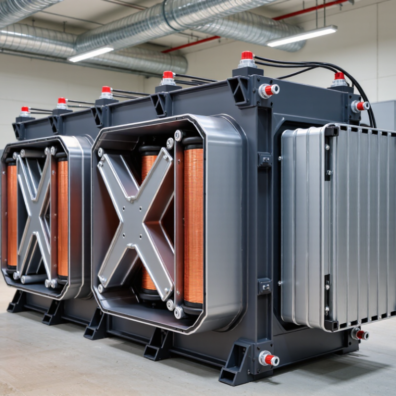
A Dry Resin Transformer is a dry-type unit with windings encapsulated in epoxy resin. The resin replaces liquid insulation around the copper or aluminum conductors. It seals the coils against moisture, dust, and many chemical contaminants. In practice, the finished winding resembles a solid, carefully molded block. No oil tank is needed. IEC 60076-11 classifies these units as dry-type transformers and addresses their insulation and temperature performance.
The operating principle remains straightforward. Alternating current enters the primary winding and creates a magnetic field in the core. This field induces a different voltage in the secondary winding. Epoxy insulation keeps the windings electrically separated while transferring heat toward the core and surrounding air. According to the U.S. Department of Energy’s Distribution Transformer Technical Support Document, distribution transformer losses were estimated at roughly 61–63 terawatt-hours annually in the United States. Small efficiency improvements therefore matter across large electrical networks.
The design is not flawless. Resin can develop cracks if manufacturing, curing, or thermal cycling is poorly controlled. Engineers must check ventilation, load patterns, altitude, and short-circuit forces before specifying a unit. A practical inspection should look for discoloration, surface tracking, unusual noise, and blocked air passages. The DOE report also shows why efficiency cannot be treated as a minor detail. A quieter, cleaner installation may still waste energy if its core losses remain high. Field conditions often expose that gap.
A Cast Resin Transformer is a dry-type electrical unit that transfers energy without liquid insulation. Its main parts work as one carefully balanced system. The core guides magnetic flux through laminated steel sheets, reducing eddy-current losses and unwanted heat. In practice, technicians inspect the core clamping, joints, and surface condition before energizing. Small gaps or loose hardware can cause vibration and audible hum.
The primary coil receives incoming voltage and creates the changing magnetic field. It usually connects to the supply side, although the arrangement depends on the system design. The secondary coil receives induced energy and delivers a different voltage to the load. Copper or aluminum conductors form controlled windings, with insulation between layers. Clearance matters. Poor spacing can weaken insulation and increase the risk of partial discharge. I have seen heat marks around a connection reveal problems that electrical readings missed.
Resin surrounds the windings and hardens into a solid insulating body. It protects against moisture, dust, and mechanical movement while transferring heat toward the cooling air. The resin must cure evenly; cracks, voids, or trapped bubbles deserve careful investigation. Not every surface mark signals failure, but dismissing one without testing is poor practice. A Cast Resin Transformer is not maintenance-free, despite that common assumption. Temperature, load history, and ventilation all affect service life. A measured inspection remains more reliable than appearance alone.
What Is a Resin Transformer and How Does It Work?
An Epoxy Resin Transformer is a dry-type transformer with windings sealed inside cured epoxy resin. Vacuum casting removes trapped air before resin hardens around the conductors. The result is a compact, sealed structure. No liquid insulation is required.
During production, technicians preheat the coil, place it inside a mold, and reduce pressure in a vacuum chamber. Degassed epoxy then flows into narrow spaces between copper layers. After curing, the resin forms a solid insulation shell. This shell limits moisture entry, dust accumulation, and partial-discharge risks. IEC 60076-11 requires dry-type transformers to undergo thermal, dielectric, and environmental testing. Practical designs often target partial-discharge levels below 10 picocoulombs, although the final value depends on geometry and testing conditions.
The process is precise, but not flawless. A small air pocket can expand during heating and weaken insulation. Resin shrinkage may also create stress around sharp conductor edges. Engineers therefore control mixing temperature, vacuum pressure, curing time, and coil cleanliness. CIGRE technical guidance identifies thermal aging and electrical stress as major factors in dry-type transformer reliability. The U.S. Department of Energy’s transformer efficiency analysis also shows why lower losses matter: distribution transformers can consume roughly 2% to 3% of national electricity in some estimates. Better encapsulation cannot remove core losses, but it can support safer operation in humid, dusty, or space-limited installations. Testing still decides the truth.
| Data Dimension | Typical Data or Range | Explanation |
|---|---|---|
| Transformer Type | Cast-resin dry-type transformer | A transformer in which the windings are insulated and mechanically supported by a solid epoxy-resin system rather than liquid oil. Cooling is normally provided by surrounding air. |
| Primary Insulation Material | Epoxy resin with mineral fillers and curing agents | The cured resin forms a rigid electrical insulation system around the winding. Fillers are commonly used to improve thermal conductivity, dimensional stability, and resistance to cracking. |
| Main Operating Principle | Electromagnetic induction | Alternating current in the primary winding produces a changing magnetic flux in the core. This changing flux induces a voltage in the secondary winding according to the turns ratio. |
| Core Construction | Laminated electrical steel core | Thin insulated steel laminations reduce eddy-current losses. The core provides a low-reluctance path for magnetic flux between the windings. |
| Winding Arrangement | High-voltage winding cast in epoxy; low-voltage winding separately insulated | The high-voltage winding is commonly encapsulated or embedded in resin. Conductive layers, insulation barriers, spacers, and cooling channels are arranged according to the required voltage and thermal design. |
| Vacuum Casting Purpose | Removal of trapped air and moisture | Vacuum reduces air pockets and volatile contaminants before and during resin impregnation. This helps improve dielectric strength, reduce partial-discharge risk, and produce a more uniform insulation system. |
| Vacuum Level Used in Processing | Process-dependent; often below atmospheric pressure to a deep vacuum | The exact pressure depends on the resin formulation, winding geometry, mold design, and production process. The target is sufficient evacuation of moisture and air without damaging the winding or causing excessive resin foaming. |
| Casting Sequence | Preheating → vacuum evacuation → resin filling → curing | Dry windings and molds are prepared first. Resin is introduced under controlled conditions, allowed to wet the insulation system, and then cured according to the resin supplier’s qualified temperature and time profile. |
| Typical Cure Temperature | Commonly about 80–160 °C, depending on resin chemistry | Curing temperature is formulation-specific. A controlled cure converts the liquid resin into a rigid thermoset material and affects mechanical strength, thermal performance, and resistance to cracking. |
| Cooling Method | Natural air cooling or forced-air cooling | Heat generated by winding and core losses is transferred through the resin, structural components, and air. Fans may be added when higher short-term or continuous loading is required. |
| Common Rated Frequency | 50 Hz or 60 Hz | The rated frequency is selected to match the electrical system. Core design, magnetic flux density, losses, and temperature rise are all influenced by operating frequency. |
| Common Voltage Range | Low-voltage secondary: up to 1 kV; medium-voltage primary: commonly several kV to approximately 36 kV | Available voltage ratings vary by application and insulation design. The required clearances, creepage distances, shielding, and resin thickness increase with voltage level. |
| Typical Power Range | Several hundred kVA to several MVA | Cast-resin transformers are widely used for building distribution, industrial facilities, renewable-energy installations, transport infrastructure, and other indoor or environmentally sensitive applications. |
| Thermal Classification | Often designed using insulation systems in the 155 °C or 180 °C thermal-class range | Thermal class indicates the temperature capability of the insulation system, not necessarily the permitted winding temperature during every operating condition. Actual limits depend on the complete design and applicable standard. |
| Moisture and Contamination Resistance | High after complete encapsulation and proper sealing | Solid epoxy reduces direct exposure of the windings to dust, moisture, and many chemical contaminants. Installation conditions and enclosure protection still affect long-term reliability. |
| Fire and Environmental Characteristics | No insulating oil; low risk of oil leakage | The absence of liquid oil eliminates oil spill concerns and reduces the amount of flammable liquid at the installation site. Fire performance depends on the complete transformer design and the qualified resin system. |
| Mechanical Protection | Rigid encapsulation with high resistance to vibration and winding movement | Once cured, epoxy supports the conductors and insulation layers, helping resist electromagnetic forces during normal operation and short-circuit events when the transformer is correctly designed. |
| Typical Electrical Tests | Winding resistance, turns ratio, insulation resistance, applied-voltage, induced-voltage, and partial-discharge tests | Routine tests verify electrical continuity, insulation integrity, voltage transformation, and the quality of the cast insulation. Additional type or special tests may be required by the project specification. |
| Applicable International Standard | IEC 60076-11 for dry-type power transformers | Dry-type transformer designs are commonly evaluated against applicable national or international standards. The exact standard and test requirements should be confirmed for the installation region and project voltage class. |
| Primary Advantages | Low maintenance, compact installation, clean operation, and reduced leakage risk | Cast-resin construction is useful where indoor installation, environmental protection, fire considerations, or reduced routine maintenance are important. |
| Important Design Limitations | Heat dissipation, resin cracking, partial discharge, and installation ventilation must be controlled | Resin transformers are not maintenance-free under all conditions. Correct loading, adequate airflow, clean surfaces, suitable ambient temperature, and periodic inspection help preserve service life. |
A resin transformer transfers electrical power through magnetic induction, not a direct connection between its windings. An alternating voltage enters the primary winding and produces a changing magnetic field in the iron core. That field crosses the secondary winding and induces a new voltage. The core guides the magnetic flux efficiently.
Frequency matters. At 50 or 60 Hz, the alternating current reverses its direction every half cycle. This changing flux continuously pushes electrons in the secondary winding. The turns ratio controls the voltage: more secondary turns usually produce a higher voltage, while fewer turns reduce it. Power changes form, not magically.
The windings are commonly sealed in solid resin. This insulation helps resist moisture, dust, vibration, and accidental surface contamination. It also supports the coils mechanically, which matters when current creates strong electromagnetic forces. During operation, heat still develops in the copper and core. Airflow, temperature sensors, and correct loading help control it.
The ideal diagram is too clean. Real units lose energy through winding resistance, core hysteresis, and stray magnetic flux. A technician may check insulation resistance, winding continuity, temperature, and unusual noise before energizing the transformer. These checks do not prove perfect operation, but they reveal many practical faults. A resin body can protect internal parts, yet it cannot correct poor ventilation or sustained overload. The magnetic principle is simple; reliable performance depends on careful design and installation.
A resin transformer is a dry-type transformer with windings sealed in solid epoxy resin. The resin provides electrical insulation and protects copper conductors from moisture, dust, and vibration. Unlike oil-filled transformers, it contains no liquid insulation. Heat must leave through solid materials and surrounding air.
Heat starts inside the windings and core. Resin conducts this heat toward the coil surface, where moving air carries it away. Natural air cooling, called AN cooling, uses convection. Warm air rises through ventilation openings, while cooler air enters below. Some installations use fans for forced-air cooling when loads increase. Small temperature sensors can monitor winding hot spots before damage occurs.
Airflow needs space. Blocked vents, heavy dust, or high room temperatures can reduce cooling performance. In practical inspections, technicians check clearances, fan operation, and unusual smells or discoloration. A clean room helps, but engineers sometimes overestimate its effect. Resin does not make the transformer immune to overheating. It only changes how heat and insulation are managed. Designers must match transformer capacity with the site’s ventilation, altitude, and load pattern. Even a brief overload can create heat faster than air can remove it. That detail is easy to miss.
A Resin Insulated Transformer uses epoxy resin to surround and support its windings. This solid insulation replaces liquid oil and limits moisture movement. In practical installations, the winding surface feels dry and rigid, not wet or flexible. The design also reduces fire risk because no flammable insulating liquid is present.
Class F insulation has a thermal class of 155°C under IEC 60085. This figure is not the normal operating temperature. It represents the insulation system’s maximum reference temperature, including ambient temperature and winding temperature rise. Under IEC 60076-11, designers must also assess heat transfer, partial discharge, and environmental conditions. A typical 40°C ambient leaves about 115 K for temperature rise. That margin can shrink quickly in a dusty room with blocked ventilation.
Thermal aging remains the critical issue. The insulation may survive short overloads, but repeated heating weakens resin and accelerates winding deterioration. The U.S. Department of Energy’s 2023 Distribution Transformers Technical Support Document highlights that transformer losses continue throughout service life, making efficient thermal design economically important. A Resin Insulated Transformer with lower losses usually produces less internal heat. Small differences matter over decades.
The 155°C rating can be misunderstood. It does not excuse poor ventilation, overloaded circuits, or careless temperature monitoring. That assumption can fail. Field inspections should check connection tightness, airflow, surface temperature, and unusual noise. In my view, manufacturers sometimes present the rating too simply; real reliability depends on the complete insulation system and the installation environment.
A resin transformer is a dry-type transformer with windings enclosed in cured epoxy resin. It transfers electrical energy through electromagnetic induction, without mineral oil or another liquid medium. The resin provides insulation, mechanical support, and protection from moisture and dust. Under IEC 60076-11, cast-resin transformers can be designed for systems with the highest voltage for equipment up to 36 kV.
Efficiency depends strongly on operating load. No-load losses come mainly from the magnetic core and continue while the transformer remains energized. Load losses increase with winding current and include conductor resistance and stray losses. A lightly loaded unit may show poor practical efficiency, even when its rated efficiency looks excellent. At a workshop test, engineers should compare no-load loss, load loss, impedance, and temperature rise at the declared rating.
Voltage rating needs careful reading. A 20 kV system does not automatically require a transformer rated at exactly 20 kV. The selected unit must match insulation levels, service conditions, and the applicable equipment voltage. IEC 60076-11 testing can include dielectric withstand, partial discharge, and thermal performance checks. Resin insulation reduces fire risk, but it does not remove heat-management problems. Ventilation, spacing, and clean air still matter. A neat datasheet can mislead if installation temperature differs from the test conditions. Small details decide reliability.
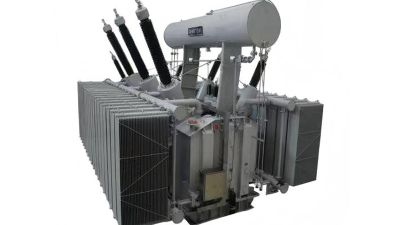
A 220kV oil-immersed power transformer is a critical main transformer for high-voltage substations, regional grids, and large power-generation facilities. Using mineral insulating oil for both dielectric insulation and heat dissipation, it transfers energy between the 220kV network and lower-voltage systems such as 110kV, 35kV, and 10kV. Typical applications include long-distance transmission, photovoltaic and wind-power step-up stations, and main step-down substations serving energy-intensive industries including metallurgy and chemical production.
For dependable operation, the transformer should be designed and tested in accordance with the applicable IEC 60076 series, covering insulation systems, temperature-rise limits, dielectric tests, short-circuit withstand capability, and routine performance verification. Mineral insulating oil should meet relevant requirements of IEC 60296, while bushings, tap changers, protection devices, and cooling equipment require coordinated specification for high-voltage service. The need for this equipment is increasing alongside grid expansion: according to IRENA’s *Renewable Capacity Statistics 2024*, global renewable capacity expanded by approximately 473 GW in 2023, reaching about 3,870 GW. This growth requires robust step-up infrastructure and stable substation transformers to manage fluctuating generation, maintain voltage control, and support secure power delivery across heavily loaded transmission networks.
It is a dry-type transformer with copper or aluminum windings sealed in cured epoxy resin. No liquid insulation is used. The winding resembles a solid molded block.
Alternating current enters the primary coil and creates a changing magnetic field. The core guides this field. The secondary coil then receives a different voltage through electromagnetic induction.
The main parts are the laminated steel core, primary coil, secondary coil, and epoxy resin. Each part has a specific job. Loose clamping hardware may create vibration and audible humming.
It seals the coils against moisture, dust, and many chemical contaminants. It also supports the windings mechanically. Trapped bubbles, voids, or cracks require investigation.
No. That assumption is wrong. Technicians should inspect temperature, ventilation, load history, surface tracking, discoloration, and unusual noise. A clean surface can still hide trouble.
Core losses continue while the transformer remains energized. Load losses rise with winding current and conductor resistance. A lightly loaded unit may perform poorly in practice.
Some units can support equipment voltage ratings up to 36 kV. The selection must match insulation levels and service conditions. A 20 kV system does not always need a 20 kV rating.
Engineers should check ventilation, altitude, spacing, load patterns, and short-circuit forces. Blocked air passages can increase temperature. Small installation mistakes matter.
Useful checks include no-load loss, load loss, impedance, temperature rise, dielectric withstand, and partial discharge. Visual inspection alone is not enough. Measurements remain more reliable.
A Resin Transformer is a dry-type electrical unit that uses epoxy resin to encapsulate and protect its windings instead of relying on liquid insulation. Its main components include a magnetic core, primary coil, secondary coil, and resin insulation system. During vacuum casting, the windings are placed in a controlled environment where epoxy resin fills gaps and forms a solid, moisture-resistant structure. This design improves mechanical strength, limits contamination, and supports reliable operation in demanding installations.
When alternating current at 50 or 60 Hz flows through the primary coil, magnetic induction transfers energy through the core to the secondary coil, changing the voltage as required. Heat is released through natural or forced air cooling, eliminating the need for insulating oil. Class F insulation provides a thermal rating of 155°C, while careful construction helps control electrical losses and maintain efficiency. Depending on the design, these transformers can support voltage ratings up to 36 kV and are evaluated under IEC 60076-11.